 The rather large box also included these instructions.
 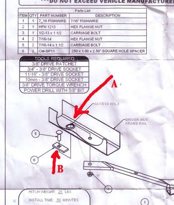 After carefully reading them, The Fuzz thought, "This should be easy" and crawled under the car. This was when the rain began. But The Fuzz is not one to be intimidated by a little shower.
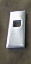
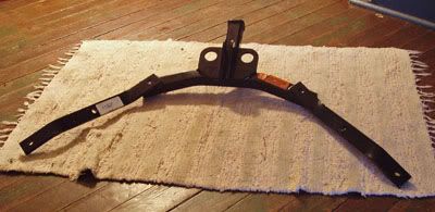
The first thing was to lower the muffler. This turned into quite a struggle, but was eventually accomplished. Next the now saturated Fuzz turned his attention to the actual installation. The holes all lined up perfectly, but now, there was a slight hitch. The part at the left (also seen at B on the diagram above) was just slightly too wide to slip up into the "Access Hole" at A. Unlike the diagram, this bit of what goes for a "frame" on these little cars, is completely boxed in. The instructions called for running a "Fishing" wire in one hole, and out the other thus pulling the bolt and this "Square Hole Spacer" across to the other hole, and then down into position to bolt the hitch to the "Frame". But this of course, presupposes that one can actually get the piece in there.
This was the point where the now thoroughly soaked Fuzz packed it in for the day.
To be continued.....
3 comments:
That looks like fun. You have to get the backing plate in the right place, then get the bolt to fall in the proper place - without losing anything in the process.
If that bolt gets away from you in that frame - well lets just say I would not be too happy.
Seems to me that it would have been better to design the thing to either have the bolt as part of the plate (one piece) or put threads on the plate so it becomes the plate and the nut.
They won't fit though the "access hole" together. They have to be assembled inside that thing. But there is a way to do it.
Yea. Make the access hole larger with a drill. No problem.
I still think the design could have been better.
Post a Comment